
Using Your Crystal Shortwave Radio
| Home: | Projects: | Crystal Shortwave Radio |
Your "EconOceanic" radio is completely assembled. Now for the exciting part—using it! This description may sound harder at first than it really is in practice. We'll go through the process simply because it's a little more involved than using
Step 1. Connect antenna and ground. Connect your antenna and ground wires to the appropriate terminals on the front panel. If you are using the telescoping antenna, it is already connected, of course.
Step 2. Connect listening device. Plug in your 2000-ohm headphones or, better yet, use Radio Shack's amplified speaker so everyone can listen at the same time. The amplified speaker is a transistorized amplifier connected to an internal speaker. It also has a 1/8-inch phone jack, allowing you to listen without disturbing others.
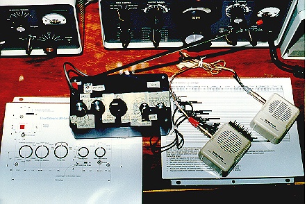
The author connected the output of the amplified speaker to a good quality high fidelity speaker. Later, the author added a second amplified speaker to the radio. The second stage amplifies the weakest signals to audible levels and easily fills the room with sound. This diagram explains the connections:
| Connect this . . . | To this |
| EconOceanic output jack | Input jack of first amplified speaker |
| Output jack of first amplified speaker | Input jack of second amplified speaker |
| Output jack of second amplified speaker | Hi-fi speaker |
This photo shows the author's prototype, with temporary labels on the panel, connected to two amplified speakers in series.
Step 3. Choose a Station. Depending upon the time of day and your location in the world, you can tune across the SW bands and listen in on broadcast activity. Some of the SW bands are more active in the evening hours, while others operate during the day.
Consult a schedule of shortwave broadcasts and note the time of day and frequency at which a desired broadcast will occur. Schedules are published in SW hobbyist magazines available at better newsstands. You can also find many schedules on the WWW. Try searching for something like "shortwave schedule" using one of the major search engines, such as http://www.excite.com/ or http://altavista.digital.com/. Another excellent resource, especially if you're new to shortwave listening, is the book Passport Guide to World Band Radio, which is described at http://www.passband.com/pages/abopass.htm.
Step 4. Look up tuner settings. Use the Bar Graph of Continuous Coverage to find the correct capacitor and coil settings to tune in the desired frequency. Print this chart using your printer's landscape mode so that it will fit on a single 8.5x11-inch sheet.
As you become more familiar with the principles of resonance, you will find that you can tune the receiver to the desired frequency by thinking about the resonance formula and selecting coils and capacitors according to the following logic:
| Low-frequency Broadcasts | High-frequency Broadcasts |
| Most capacitance | Least capacitance |
| Longest coil | Shortest coil |
For example, to tune the AM broadcast band, you would select your longest coil (250uH) and your biggest capacitor setting (460 pF). Similarly, to tune the highest shortwave frequencies, you would select your shortest coil (10uH) and your smallest capacitor setting (7 - 9 pF).
It's possible to receive the same broadcast signal with different combinations of coils and capacitors. The best combination is the one at which the incoming signal is loudest. Experiment and learn the best settings. You can also combine dissimilar primary and secondary coils to receive radio signals. That is, you can set the antenna coil to 250uH and the tuning coil to 20uH and you will receive SW signals. This occurs because of the inductive coupling effects of the multiple coils on the same coil form.
Remember that the tuning coil alone determines the frequency at which radio signals will be received. The tuning coil resonates with the tuning capacitor. The antenna coil merely feeds the incoming radio waves to the tuning coil. Enjoy this advantage of mounting several adjacent coils on the same core.
Step 5. Turn the antenna coil selector switch to a desired primary coil.
Step 6. Rotate the tuning coil selector switch to the associated secondary coil.
Step 7. Turn the band capacitor selector switch to a desired setting. Now the band is selected.
Step 8. Rotate the tuning capacitor to select a broadcast signal within the selected band.
Step 9. Starting at the lowest setting of the "low" bandspread scale, adjust the bandspread switch for maximum broadcast signal loudness.
Step 10. If you are using the amplified speaker, adjust the volume to a comfortable setting. If you are using a pair of unamplified, 2000-ohm headphones, there is no loudness control.
Step 11. Log your settings. On a sheet of paper, write the time of day, the settings of your selector switches, and a description identifying the source of the broadast signal. For example, you might write:
9 p.m. EST, 20uH A coil, 20uH T coil, 13 - 19 pF, Radio Havana (Cuba) 8.9 MHz.
Logging your reception reports will help you locate your favorite radio broadcasts. Documenting your work also adds a hint of substance and credibility to your DX sessions. Above all, have fun!
If you completed this project and enjoy using your EconOceanic, please drop us a line and share your experiences. Walter's email address is walterh@interworld.com.
Copyright 1997 Walter Heskes and Philip I. Nelson, all rights reserved. This radio construction project, including all descriptions, diagrams, photos, and the underlying electronic design, is published here for the noncommercial use of radio hobbyists. You may print and reproduce these project instructions for your personal use. Commercial use of this material is strictly forbidden.